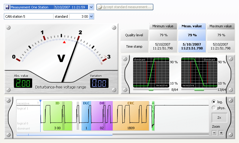
Why is it important to measure on physical layer in CAN bus?
Our world is analog. Digital is a human invention to simplify many things. Smoke signals between mountain peaks, signal lights between ships, Morse signals on air – all these already were digital signals. As long as digital works, it is invincible – for instance in the precision of transmission. But even when you transmit digital signals, you need an analog medium below it. Such a medium is failure-prone. Smoke signals fail in darkness, signal lights are useless in foggy conditions, Morse signals are going to be inaudible when interfering signals are too loud.

On a Fieldbus and in electronics in general, voltages are defined to represent digital High and Low. Because everybody knows that voltages are analog values, an illegal range is defined where no signal is supposed to be. To get a certain amount of transmission reliability, in normal conditions the voltages are defined in a distance to this illegal range.
To signal a voltage you need a wire as the medium. What works easy in a flashlight, gets difficult on high frequencies and long trunk lines very quickly. Then we talk about capacities and frequencies, not only about resistors and switches. You will need more than good knowledge and a multimeter to get useful and repeatable statements.
Somebody could say that at problems in a CAN bus communication, error frames and repetition of messages occur. This is not quite correct. We have to say that at a point where error frames are on the bus, we can not speak from a hitch-free digital transmission anymore. The bus can still run because of the work of the safety mechanisms in CAN, repeating not correct transmitted messages. At this point, only a little worsening would lead to a complete breakdown of communication. That’s why we have to state that permanent error frames (on a former good running bus) are an indicator for a nearby total failure. Sometimes this level of worsening never happens and the bus just stops working.

What happens? Machines are aging, wires getting brittle and break, connectors getting wet and corrode, components in sensors and actuators are subject to aging effects. The distance of voltages to the illegal range is shrinking, frequencies are shifting, capacities degrade signals. Besides aging, the interference resistance plays a roll on this. What works great on a lab table, may not work beside other machines or mobile on the road.
How can I gage, how good the digital transmission works, when the only thing I know is that it works?
We should measure, how the distance to the illegal range of voltages is – how much wear reserve is left – how much interference resistance we have for the work in the field. We should measure, if the quality of signals is worse than at the other day or if it is as good as new.
This works only on measuring, evaluating and comparing analog values, deep down on the CAN physical layer. You can do this the classic way using an oscilloscope. You will need expert knowledge and experience. A device that evaluates the measured values instead of just showing a visualization of a signal, is much more helpful. When you can get a direct compare with an older measurement or another measurement point within the bus, even troubleshooting will be much easier.
For this purpose are the GEMAC Fieldbus tools. A technician is able to say something about signal quality in a short time. Even to go through an acceptance test can be done in minutes and gives clear statements, which can easily be printed. On troubleshooting, it is possible to quickly isolate where a problem is. The outcome of maintenance and repairs can be evaluated in terms of numbers.
What do you know without measurement? Only that it works or not. Without a measurement device you stay with the digital “Zero or One”-statement. With a measurement device, your eyes are opened to a whole new world, the analog world we are living in.


